
How Can I Use Hybrid 3D Printing for Industrial Aerospace Spare Parts?
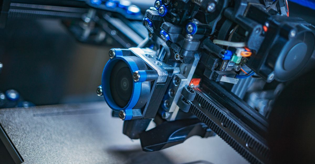
The aerospace industry demands high‑strength, low‑weight components that meet strict certification standards. Traditional manufacturing methods—machining, casting, or additive only—often fall short when rapid prototyping and on‑demand production are required. Hybrid 3D printing blends the precision of FDM or SLA with the material versatility of powder bed fusion, delivering parts that satisfy aerospace criteria while keeping costs manageable.
Hybrid 3D Printing Basics
Hybrid systems combine two additive technologies in one build chamber. The most common pairings are FDM (or resin) for fine geometry and PBF for dense load‑bearing sections. This layering allows complex internal lattices with solid outer shells without costly machining.
When evaluating a machine, consider build volume, material compatibility, and software integration. A well‑configured system transfers toolpaths seamlessly between modalities so the design can be split into zones based on performance needs.
Typical Hybrid Configurations in Aerospace
- PBF + FDM: Titanium core with a PETG or Nylon skin reduces weight while preserving strength.
- SLA + PBF: SLA for optical elements, followed by an aluminum layer that adds structural support.
- Multi‑Material FDM + PBF: Carbon fiber filaments in stiff regions; powder fusion fills critical load paths with titanium or AlSi10Mg.
Hybrid printers often feature integrated atmosphere control, switching between inert gas for powder processing and a dry environment for filament extrusion to avoid cross‑contamination.
Industrial Aerospace Needs
Aerospace spare parts must meet weight limits, fatigue resistance, thermal stability, and rapid production. Hybrid printing lets you tailor each region: PBF‑sintered titanium or aluminum cores with FDM‑printed polymer skins reduce mass while improving finish.
Rapid iteration is also possible; if a lattice flaw is detected during inspection, only that section needs adjustment, saving time and material.
Certification Context
Regulations such as FAA Part 21 or EASA CS‑22/CS‑23 require traceable materials, rigorous mechanical testing, and non‑destructive evaluation. Hybrid manufacturing produces a single part that meets these criteria while allowing features—like internal cooling channels—that conventional methods cannot.
Weight & Fatigue Considerations
The graded density capability of hybrid printing localizes high‑stress regions with dense lattices, keeping low‑stress areas lightweight and mitigating fatigue cracks.
Material Selection for Hybrid Systems
Key Material Pairings
- Titanium alloy (Ti‑6Al‑4V) – PBF for high strength cores.
- Aluminum 6061 – PBF for lightweight structural elements.
- Nylon 12 or PETG – FDM for flexible, low‑stress skins.
- Polycarbonate resin – SLA for optical clarity where needed.
- Carbon fiber reinforced polymer – hybrid for high stiffness-to-weight ratio.
The choice depends on the part’s load profile. Pairing Ti‑6Al‑4V with PETG often meets certification weight limits while enabling rapid prototyping of complex geometries. Always verify that each material is certified for aerospace use.
Surface Finish and Post‑Processing
Polymer skins may need mild post‑processing, such as solvent vapor polishing for PETG, to achieve the low surface roughness required by aerodynamic regulations. Metal cores benefit from heat treatment cycles that relieve residual stresses introduced during sintering.
Compatibility of Powder and Filament
Select materials with matching thermal expansion coefficients to avoid interlayer delamination or micro‑cracking at the interface. For example, a high‑temperature polymer like PEEK may need an aluminum alloy bridge when paired with Ti‑6Al‑4V.
Design and CAD Workflow
Split your CAD model into material zones before exporting to the hybrid slicer. The outer shell, printed by FDM, can accommodate tolerances and surface finishing, while the inner lattice—handled by PBF—provides necessary strength.
Design Checklist
- Define material zones for high‑density areas.
- Add build orientation markers to reduce support need.
- Use lattice tools (e.g., 3D‑Print‑Lab) for internal void optimization.
- Apply anisotropic reinforcement where directional loads exist.
- Include fillets and chamfers to lower stress concentrations.
Separating the model into distinct material zones early prevents costly re‑slicing later.
Topology Optimization Integration
Run a topology optimization that considers both materials’ properties. The optimizer will suggest where to place high‑density cores versus low‑density skins, ensuring the part meets stiffness and mass targets while remaining manufacturable.
Slicer Configuration
Hybrid slicers expose settings for each module—layer height, infill density, support type. Configure PBF with dense 100 % infill and minimal supports; FDM can use a lower layer height (e.g., 0.1 mm) and lattice infill matching the core’s pore structure.
Build Process Steps
The hybrid build typically follows two stages: first, PBF prints dense cores or structural features; then FDM adds finishing layers. Timing is crucial to keep the core dry and stable before polymer deposition.
Step‑by‑Step Guide
- Preheat the chamber for both processes.
- Load titanium or aluminum powder into the PBF head and start printing.
- At a defined height, pause and transfer to the FDM station.
- Extrude PETG or Nylon for outer layers.
- Cool and remove supports in a controlled environment.
Atmosphere Control & Powder Handling
PBF requires an inert gas (usually argon) to prevent oxidation. The chamber automatically switches from inert to ambient air or dry nitrogen when transitioning to FDM, protecting the filament from high temperatures.
Support Strategy
PBF relies on powder support for overhangs, so supports are minimal. FDM skins may need small, low‑density supports that can be removed with little surface damage.
Post‑Processing
After printing, parts undergo controlled cooling to reduce residual stresses in the metal core. The polymer skin is cleaned with an isopropyl alcohol rinse and dried at room temperature. If surface roughness exceeds specification, a light sanding or polishing step brings it within tolerance.
QA & Testing Protocols
Aerospace parts must pass NDT, dimensional inspection, and mechanical certification. Hybrid printing introduces interfaces that require careful QA to prevent delamination or internal defects.
Testing Checklist
- Optical microscopy of interface seams for micro‑cracks.
- CT scanning to verify lattice integrity.
- Tensile testing on core samples to confirm strength.
- Thermal cycling tests for material compatibility.
- Surface roughness measurement where regulatory thresholds apply.
A single CT scan of the hybrid interface often revealed hidden porosity that would have failed certification if left unchecked.
NDT Methods Specific to Hybrid Parts
- Ultrasonic testing detects subsurface delamination between metal core and polymer skin.
- Dye penetrant inspection reveals surface cracks on the outer shell.
- X‑ray imaging provides a full volumetric view, ensuring no voids remain within the lattice.
Mechanical Testing Protocols
For structural components, perform tensile and bending tests that isolate core material performance. When testing hybrid parts, also evaluate interfacial shear strength by applying a load that forces the two materials to slide against each other.
Cost Analysis & ROI
The upfront cost of a hybrid printer can be high—$200k to $500k for industrial‑grade machines. However, material savings, reduced machining time, and on‑demand production yield a clear return on investment.
Calculate ROI by comparing traditional manufacturing costs (material + CNC machining + tooling) against hybrid production costs (powder/filament cost + machine depreciation). Typically, a hybrid part that would take 10 hours of CNC machining can be printed in under an hour, cutting labor costs dramatically.
Material Cost Breakdown
Titanium powder is expensive per kilogram, but PBF uses only the necessary volume for the core while the polymer skin remains lightweight. Surplus powder often recovers and reuses, further reducing expenses.
Depreciation & Maintenance
Hybrid machines have two consumables: powder for PBF and filament for FDM. Each requires periodic calibration, but overall maintenance aligns with single‑technology printers when properly managed. Factoring depreciation over a five‑year life cycle shows high‑volume aerospace suppliers can break even within 18–24 months.
Life‑Cycle Assessment
A hybrid part reduces environmental impact by eliminating multiple downstream processes—machining, drilling, surface finishing—into one build, cutting energy use and waste generation.
Common Pitfalls and Fixes
Hybrid printing is powerful but not without challenges. Below are frequent issues and how to mitigate them.
Top Mistakes & Remedies
- Material mismatch: Ensure powder and filament share compatible thermal properties to avoid adhesion problems.
- Orientation errors: Misaligned build axes introduce stress risers—optimize orientation in CAD first.
- Support overuse: Excess supports damage surfaces; use minimal support strategies and careful post‑processing.
- Inadequate curing: Post‑heat treatment is essential for PBF parts; skipping it leads to warping.
- Ignoring certification standards: Align material grades with FAA or EASA requirements before production.
Troubleshooting Interface Issues
If delamination appears between metal core and polymer skin, apply a two‑step bonding approach: first, a thin layer of thermally compatible adhesive (e.g., epoxy curing at 120 °C) before the FDM step; second, a low‑temperature anneal to promote adhesion without compromising polymer properties.
Powder Reclamation Challenges
PBF machines recover unbound powder after each build. Contamination from residual polymers reduces reusability. Implement a dedicated cleaning station where powder is vacuum‑filtered and rinsed with an appropriate solvent before returning to the hopper.
Software Glitches
When slicing hybrid models, software may misassign material zones or generate overlapping toolpaths. Verify each slice file in preview mode, ensuring that the PBF portion stops precisely where the FDM section begins.
By following these guidelines, you can harness hybrid 3D printing to deliver high‑quality aerospace spare parts efficiently and cost‑effectively.
What challenges have you encountered when integrating hybrid 3D printing into your aerospace supply chain?


